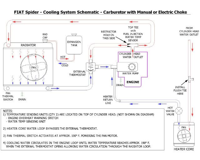
Cooling Systems Schematic Diagram
-
donerehart
- Posts: 344
- Joined: Fri May 14, 2010 9:29 pm
- Your car is a: 1976 spider
Re: Cooling Systems Schematic Diagram
Thanks for all your work with this Wheel!
76 Spider
St. Louis, MO
St. Louis, MO
-
vandor
- Posts: 3996
- Joined: Sat May 23, 2009 1:23 pm
- Your car is a: 1971 124 Spider
- Location: Texas, USA
Re: Cooling Systems Schematic Diagram
I think it's more likely that there was air in the heater core, and it created an air bubble in the cooling system when you opened it.Wheel wrote: As I mentioned, it happened shortly after I turned the heater on, so I am kind of suspecting an air bubble as you suggest. Do you think that the coolant may have just been circulating in the heater core loop, bypassing the thermostat?
It would flush and refill the system with the heater valve open, and see what happens.
Csaba
'71 124 Spider, much modified
'17 124 Abarth, silver
http://italiancarclub.com/csaba/
Co-owner of the best dang Fiat parts place in town
'71 124 Spider, much modified
'17 124 Abarth, silver
http://italiancarclub.com/csaba/
Co-owner of the best dang Fiat parts place in town
- Wheel
- Posts: 112
- Joined: Sun May 08, 2011 6:18 pm
- Your car is a: 1982 Fiat Spider
- Location: Saskatoon, SK, Canada
Re: Cooling Systems Schematic Diagram
Diagram for the Carb, Water Choke Version

Diagram for the Carb, Manual Choke or Electric Choke


Diagram for the Carb, Manual Choke or Electric Choke

1982 Fiat Spider
- Wheel
- Posts: 112
- Joined: Sun May 08, 2011 6:18 pm
- Your car is a: 1982 Fiat Spider
- Location: Saskatoon, SK, Canada
Re: Cooling Systems Schematic Diagram
I have posted a .pdf version of each diagram on Google Docs for anyone to download. The image is larger and clearer. It should print nicely on 8.5" x 11" paper. Copy the https address into your browser address bar. Download the original.
Cooling System Schematic – FIAT Spider, Fuel Injection
https://docs.google.com/open?id=0B3XBQI ... kwMWY0MDFl
Cooling System Schematic – FIAT Spider, Carburetor with Water Choke
https://docs.google.com/open?id=0B3XBQI ... IxMGU3ODFm
Cooling System Schematic – FIAT Spider, Carbureted with Manual or Electric Choke
https://docs.google.com/open?id=0B3XBQI ... dhNzA4MDkw
Let me know if it works out. This is my first time doing this.
1982 Fiat Spider
-
donerehart
- Posts: 344
- Joined: Fri May 14, 2010 9:29 pm
- Your car is a: 1976 spider
Re: Cooling Systems Schematic Diagram
These are superb! Great work and thanks for sharing!
Don
Don
76 Spider
St. Louis, MO
St. Louis, MO
-
blusmith
- Posts: 82
- Joined: Sun May 29, 2011 3:00 am
- Your car is a: 1982 124 spyder
Re: Cooling Systems Schematic Diagram
Thanks . that will help get my flows correct . Chris
- RRoller123
- Patron 2020

- Posts: 8179
- Joined: Sun Nov 13, 2011 2:04 pm
- Your car is a: 1980 FI SPIDER 2000
- Location: SAGAMORE BEACH, MA USA
Re: Cooling Systems Schematic Diagram
Excellent!
'80 FI Spider 2000
'74 and '79 X1/9 (past)
'75 BMW R75/6
2011 Chevy Malibu (daily driver)
2010 Chevy Silverado 2500HD Ext Cab 4WD/STD BED
2002 Edgewater 175CC 80HP 4-Stroke Yamaha
2003 Jaguar XK8
2003 Jaguar XKR
2021 Jayco 22RB
2019 Bianchi Torino Bicycle
'74 and '79 X1/9 (past)
'75 BMW R75/6
2011 Chevy Malibu (daily driver)
2010 Chevy Silverado 2500HD Ext Cab 4WD/STD BED
2002 Edgewater 175CC 80HP 4-Stroke Yamaha
2003 Jaguar XK8
2003 Jaguar XKR
2021 Jayco 22RB
2019 Bianchi Torino Bicycle
-
SpecialTool
Re: Cooling Systems Schematic Diagram
I just replaced the heater control valve in my '75 and noticed it was connected to the line from the head (opposite from the diagram), thus blocking hot coolant from entering when closed. Should it be the other way around? The inlet should be the lower of the pipes on the heater core to allow any air to escape into the rest of the system and, hopefully, eventually to the expansion tank via the radiator, right?