Cooling Systems Schematic Diagram

Keep it on topic, it will make it easier to find what you need.
Post Reply
User avatar
Wheel
Posts: 112
Joined: Sun May 08, 2011 6:18 pm
Your car is a: 1982 Fiat Spider
Location: Saskatoon, SK, Canada

Cooling Systems Schematic Diagram

Post by Wheel »

My Spider over-heated last week after a few minutes of driving, sending coolant out the expansion tank. The outside air temperature was a few degrees above freezing. The radiator fan did not kick in. It seemed to happen after I opened the heater valve. I am not sure if it is an air in the system, a bad thermostat, a failed fan thermal switch or if the heater cooling loop was just by-passing the thermostat. Anyways, I was planning on replacing the cooling system components anyway. I was just waiting to park the car for the winter.

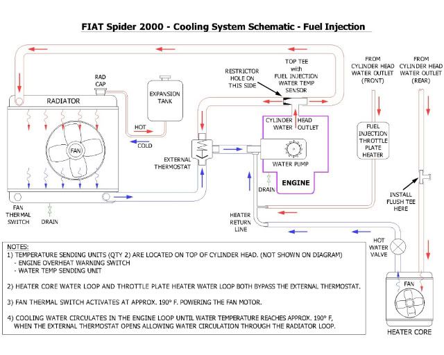
I couldn’t seem to find a diagram that showed all the cooling water loops in one single diagram, so I drew one up based on information from others on this site and some shop manuals. The diagram is for a 1982 Spider, fuel injected.
Image

Are any corrections needed? Any suggested improvements? Let me know your thoughts, I will update and re-post the diagram as required.
Last edited by Wheel on Tue Nov 08, 2011 9:07 pm, edited 2 times in total.
1982 Fiat Spider
User avatar
azruss
Posts: 3659
Joined: Sun May 30, 2010 12:24 pm
Your car is a: 80 Fiat 2000 FI

Re: Cooling Systems Schematic Diagram

Post by azruss »

nice drawing. what cad program do you use. 2 things. the valve in the stadt should be located in the lower radiator hose so when it is closed it only closes the lower radiator hose. the way you have it, it closes both hoses. Also, you may want to add which side of the coolant tee the restrictor hole is on.
vandor
Posts: 3996
Joined: Sat May 23, 2009 1:23 pm
Your car is a: 1971 124 Spider
Location: Texas, USA

Re: Cooling Systems Schematic Diagram

Post by vandor »

Nice diagram!

If it was that cold the rad fan would normally never come on.
Sounds like an air pocket or stuck thermostat - mind you I've never seen one stuck closed, but it could happen.
Did you do any cooling system work just before this happened?
Csaba
'71 124 Spider, much modified
'17 124 Abarth, silver
http://italiancarclub.com/csaba/
Co-owner of the best dang Fiat parts place in town
User avatar
Wheel
Posts: 112
Joined: Sun May 08, 2011 6:18 pm
Your car is a: 1982 Fiat Spider
Location: Saskatoon, SK, Canada

Re: Cooling Systems Schematic Diagram

Post by Wheel »

Thanks for the comments. I used Autocad to create the schematic. I updated the drawing and it is reloaded.

Azruss, I rotated the thermostat as you pointed out. Can you tell me more about the restrictor hole? I do not know what this is or where it should be.

Vandor, I bought the car in mid-August and have not done any work to it. I am not sure what the PO might have done. All the coolant parts look original so I suspect if he did anything it would have only been a coolant flush. As I mentioned, it happened shortly after I turned the heater on, so I am kind of suspecting an air bubble as you suggest. Do you think that the coolant may have just been circulating in the heater core loop, bypassing the thermostat? I read this scenario in another posting. Would the bottom of the rad be cool enough to keep the fan from switching on, but the top of the rad got hot enough to boil out the expansion tank? It doesn't seem to make sense, but I am unsure.

What does stadt mean? I am assuming it is the thermostat. Is this mechanic jargon?

Does the diagram need any other corrections?
1982 Fiat Spider
User avatar
azruss
Posts: 3659
Joined: Sun May 30, 2010 12:24 pm
Your car is a: 80 Fiat 2000 FI

Re: Cooling Systems Schematic Diagram

Post by azruss »

what you have listed as the top tee has a restricted hole on the stadt (lazy for thermostat) side. when you look at the Tee, it isnt obvious which side the restrictor side should be on. I'm guessing the hole on that side is about 1/2"
User avatar
Wheel
Posts: 112
Joined: Sun May 08, 2011 6:18 pm
Your car is a: 1982 Fiat Spider
Location: Saskatoon, SK, Canada

Re: Cooling Systems Schematic Diagram

Post by Wheel »

Azruss, I updated the diagram. Please check to see if I interpreted your description correctly.
1982 Fiat Spider
dmwhiteoak
Posts: 1088
Joined: Mon Aug 15, 2011 1:12 pm
Your car is a: 1972 Fiat 124 spider
Location: White Oak Tx

Re: Cooling Systems Schematic Diagram

Post by dmwhiteoak »

Is the water flow different on a 78? I ask this because when I had no flow to the heater core it was because the steel line coming from the water pump was plugged. Once I had this unplugged water flowed from the pump,through the core and then to my flushing T and then into the head. That is totally backwards from your diagram. BTW , Good looking diagram!
Dennis Modisette

1972 124 Spider
2003 Chevrolet Z71
2007 GMC Yucon
rlux4
Patron 2022
Patron 2022
Posts: 4211
Joined: Thu Jan 10, 2008 8:32 pm
Your car is a: 1982 2000 Spider
Location: Granite Falls, Wa

Re: Cooling Systems Schematic Diagram

Post by rlux4 »

The heater core tube is connected to the suction side of the water pump, so the flow is being "pulled" through the heater core, not pushed.
This was drastically demonstrated to me on my trip up to Oregon '08 when, trying to keep up with the Fiat America gang traveling up the coast route, the bouncing of the tube caused a slight leak at the mounting flange. It wasn't bad enough to drip so it took a while to diagnose why air was being pulled into the system and displacing coolant, which boiled out of the overflow bottle. (A PO had cut off the support bracket of the tube.)
Ron
Last edited by rlux4 on Sun Nov 06, 2011 3:10 pm, edited 1 time in total.
Ron Luxmore
rlux2n2@gmail.com
'82 2000 Spider: after 26 years between Spiders.
User avatar
azruss
Posts: 3659
Joined: Sun May 30, 2010 12:24 pm
Your car is a: 80 Fiat 2000 FI

Re: Cooling Systems Schematic Diagram

Post by azruss »

I think you got it nailed. Nice job! dont know if there is any way to post it to this site as a PDF so everyone could have a copy. I have a DWG to PDF converter so could help you if interested.
dmwhiteoak
Posts: 1088
Joined: Mon Aug 15, 2011 1:12 pm
Your car is a: 1972 Fiat 124 spider
Location: White Oak Tx

Re: Cooling Systems Schematic Diagram

Post by dmwhiteoak »

Ron, Of all the cooling sys digrams that I have seen, wich ain't but a couple, you are correct. But when I unplugged my tube and installed it back on the car, water flowed from the tube instead of the head as I would have expected when I started the car. With the car running with the tube plugged all I got with the cap off the flushing T was a dribble. I should have had full flow coming off the head. I had good heat for a week until a leaking control valve took care of that. Have one on order and when I tie hoses back to the core I will investigate this further.
Dennis Modisette

1972 124 Spider
2003 Chevrolet Z71
2007 GMC Yucon
User avatar
azruss
Posts: 3659
Joined: Sun May 30, 2010 12:24 pm
Your car is a: 80 Fiat 2000 FI

Re: Cooling Systems Schematic Diagram

Post by azruss »

never mind the conversion. I see you posted it as a JPEG. I was able to copy it into a file.
donerehart
Posts: 344
Joined: Fri May 14, 2010 9:29 pm
Your car is a: 1976 spider

Re: Cooling Systems Schematic Diagram

Post by donerehart »

How would this change for a carb model? This is great!
76 Spider
St. Louis, MO
User avatar
Wheel
Posts: 112
Joined: Sun May 08, 2011 6:18 pm
Your car is a: 1982 Fiat Spider
Location: Saskatoon, SK, Canada

Re: Cooling Systems Schematic Diagram

Post by Wheel »

I can create a .pdf file and check into a way to get the file to those who may be interested. This way the image would be much better than the imbedded 640 x 480 jpg image.

I could also create a drawing for the carburetor engine. I would need to dig into this a bit more. If anyone can describe the changes easily, it may save me some time. Are there any more versions that would be nice to have?

Is the coolant flow direction correct in all the cooling loops? Just want to confirm.
1982 Fiat Spider
digitech
Posts: 336
Joined: Sun Jul 19, 2009 6:37 am
Your car is a: 1979 Fiat Spider

Re: Cooling Systems Schematic Diagram

Post by digitech »

It's correct.
User avatar
Wheel
Posts: 112
Joined: Sun May 08, 2011 6:18 pm
Your car is a: 1982 Fiat Spider
Location: Saskatoon, SK, Canada

Re: Cooling Systems Schematic Diagram

Post by Wheel »

In response to Donerehart's question;
Is the only difference the substituting of the fuel injection throttle plate heater with the carb water choke?
1982 Fiat Spider
Post Reply